KDR Line / Load Reactors

TMS & TCI for over 16 years the difference in service and power quality solutions for the canadian market.
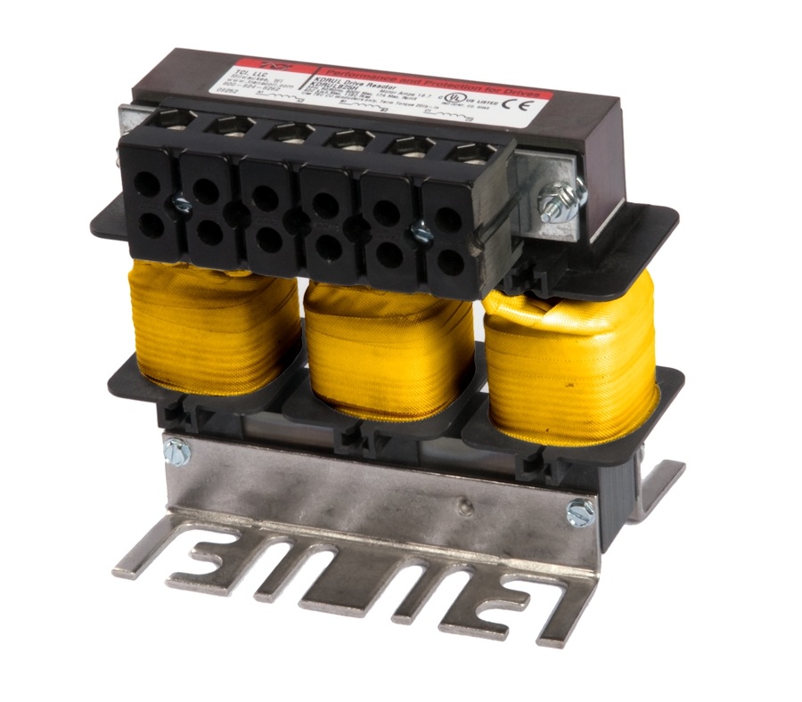
KDR Line / Load Reactors
KDR line reactors prevent nuisance tripping
- Limits expensive down-time
KDR line reactors reduce harmonic current
- Increases life of drive
- Protects sensitive equipment
Power quality has degraded over time due to the increased use of non-linear loads.
Drives and other sensitive devices are vulnerable to electrical distortion on the line.
The KDR line reactor provides a cost-effective solution to this issue.
Harmonics and Power Quality
Variable frequency drives are beneficial to a wide range of applications, but contain a power conversion process that creates current and voltage distortion which can cause system-wide problems, including:
- Transformer and distribution equipment overheating
- Random breaker tripping
- Sensitive equipment may fail completely
- Poor power factor
- Reduced system efficiency
KDR Optimized Line Reactor on Harmonics
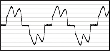
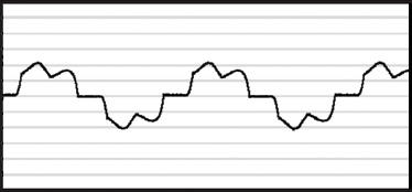
The addition of a KDR Reactor will reduce harmonic content, which reduces the total RMS current, thereby improving the total power factor.
- Nuisance tripping is less common
- Drive uptime is increased
- Power factor is improved
Harmonic Current
without KDR |
|
Harmonic Current
with KDR |
  |
|
  |
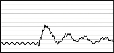
Transient Voltages cause Nuisance Tripping
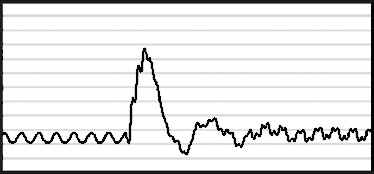
A voltage transient, commonly caused by capacitor bank switching (or other issues), sends a current surge into the VFD bus capacitor. The additional current raises bus voltage, thus causing a drive fault (trip). In addition, this overvoltage condition will cause the drive to shut down in order to protect its components.
KDR Optimized Line Reactor on Transient Voltages
The additional impedance offered by the KDR Line Reactor slows down the current surge, thus reducing the likelihood of the drive tripping offline.
| Voltage Before KDR |
|
Voltage After KDR |
 |
|
 |
Unbalanced Distribution Systems cause Nuisance Tripping
Input voltage phase unbalance may prevent the drive from performing due to subsequent overcurrent conditions which cause the drive to cease operating.
KDR Optimized Line Reactor on Unbalanced systems
The addition of a KDR Reactor to the input of every drive will help balance the drive input line currents.
Impact of additional AC Line Reactance on the DC Bus Voltage of a Motor Drive
Adding ac line reactance can be beneficial to the drive as it lowers the input current THD and peak diode current. Read the Impact of Additional AC Line Reactance technical paper for more details.
- Dampen Overshoot Peak Voltage
- Reduce Motor Heating
- Reduce Audible Noise
DIN Rail Line Reactor Option
For smaller applications incorporate DIN Rail Drive Reactors to the input and output of PWM drives for easy installation and superior performance:
- Reduce installation time and cost
- Compatible with any 35mm DIN Rail
- Mounts to "Standard Steel High Profile" or "Heavy Duty Steel" DIN Rails
- Reactor mounts horizontally on horizontal DIN Rail
- Improve organization of reactors and their cabling
- RoHS compliant
Single-Phase Line Reactor Applications
KDR Line Reactors can be used in single-phase applications. Please note that the level of impedance will be reduced from three-phase levels. Contact Technical Support 866-540-0412 for more information.
Impedance Options
The KDR Line Reactor has been designed to provide the best protection for both your drive and your application. KDR Line Reactors are available in two ratings versions, Low "Z" (low impedance, any application where a 3% reactor would be applied) and High "Z" (high impedance, any application where a 5% reactor would be applied). Input impedance can significantly improve drive performance. Select impedance based on the guidelines below:
Use KDR Low "Z" Units For:
Any application where a 3% reactor would be applied.
Reduction of nuisance tripping caused by:
- Transient voltages caused by capacitor switching
- Line notching
- DC bus overvoltage tripping
- Inverter overcurrent and overvoltage
Additional benefits include:
- Lowering injected percentage of harmonic current
- Improving true power factor
- Reducing cross-talk between drives
- Adding impedance to drives with DC link chokes/reactors when more impedance is desired due to a relatively stiff source
Use KDR High "Z" Units For:
Any application where a 5% reactor would be applied.
KDR High "Z" offers the same superior benefits as Low "Z" plus additional benefits which include:
- Helping prevent drive component damage
- Providing maximum harmonic mitigation without adding capacitance
- Further improving true power factor
- Adding impedance to drives without DC link chokes/reactors when more impedance is desired due to a relatively stiff source
KDR Specifications
- Impedance Protection: Low "Z" and High "Z"
- System Voltage: 208/240 VAC, 480 VAC, 575/600 VAC, 690 VAC
- Ambient Temperature: 50° C (122° F) - Open; 40° C (104° F) - Enclosed
- Altitude (Maximum): 2,000 meters (6,000 feet)
- Derating necessary above 2,000 meters
- Fundamental Frequency: 50/60 Hz
- Short Term Overload Rating: Tolerate 200% rated I for a minimum of 3 minutes
- Agency Approvals: cUL, UL; UL Recognized, CE Marked
- Inductance Characteristics:
- Minimum 95% L at 110% Load
- Minimum 80% L at 150% Load
- Input and Output: Available for either the line or load side of a VFD
- Enclosures: Open, UL Type 1, UL Type 3R
KDR Typical Applications
- Oil and Gas Pumps
- Irrigation Fields, Farms
- Water, Wastewater
- HVAC
- Steel Industry
- Pulp/Paper
- Machining
- Extruders
